
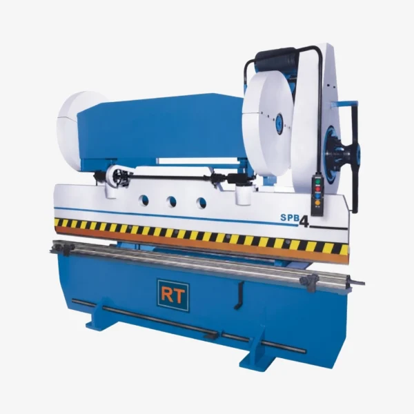
Mechanical Press Brake
The Mechanical Press Brake is designed for efficient sheet metal bending with dependable mechanical drive performance. It provides accurate bending, smooth operation, and consistent production output. Ideal for fabrication shops handling routine metal forming applications.
- Description
- Specifications
Description
RT Power Press Brakes are designed and developed through years of experience in sheet metal working machines. RT Power Press Brakes are widely accepted in industries for continuous production runs, and in areas requiring accuracy and repeatability coupled with high production.
Frame
Frame is of robust fabricated steel construction of rigid and interlocked design, It is strain- free and supports the ram and bed against undesired deflection under permissible loding condition.
Ram and Bed
Made from steel Plates of suitable thickness, machined for straightness and parallelism of the working surfaces. Ram is guided and supported throughout the stroke by accurately machined guided ways.
Drive System
Power is transmitted to the ram through two individual geardrives for uniform load distribution throughout the length. This also reduces the torsional stresses on the eccentric shaft. Electric motor used is of sufficient H.P. which reduces slowdown of flywheel and increases energy available per stroke. The gear and pinion are made out of carbon/alloy steel.
Ram Adjustment
Motorised ram adjustment through a simple drive mechanism, facilitates quick bending angle adjustment. Angular ram adjustment is made simple by incorporating a spring loaded dog clutch.
Clutch and Brake
All series of press brakes are provided with high-torque low-inertia friction clutch, synchronized with heavy duty mechanical brakes ensuring immediate braking of ram on releasing the pedal. Clutch operating levers are designed in such a way that minimum engaging force is required at the pedal.
Standard Features
- Foot Pedal and Die Block Lifting Link
- Fly Wheel & Gear Guard.
- Self Lubrication System.
- Motor Pully.
- Stroke counter.
- Standard “V” Block and Punch.
- Motor Mounting Bracket.
Options
- Motorised Back Gauge.
- Automatic Lubrication System.
- Vee-Belts.
- Electric Motor & Starter / Control Panal Board.
- Squaring Gauge System.
- Various type of Die & Punch.
- Foundation Bolts.
- All Dimensions are in mm.
- Power Supply 400/440 volts, 3 Phase, 50 Cycle.
- As day to day improvements are contemplated for better performance of the machine. We reserve the rights to alter the specifications without prior notice.
- All the machines undergo a through check-up by our expert engineers before dispatch to ensure their smooth and trouble free operation.
| Model | Capacity in Tons | Bending Cap. (Length × Thick.) |
Dist. Between Housing | Stroke Length | Stroke per Minute | Ram Adjustment | Shut Height Ram Stroke Down |
Table Height | Depth of Throat | Main Motor H.P. | Ram Adjustment Motor H.P. | Die Space (Length × Width) |
Machine Dimensions (L × W × H) |
Approx. Weight Kgs. |
|---|---|---|---|---|---|---|---|---|---|---|---|---|---|---|
| RMP215 | 20 | 1525 × 1.6 | 990 | 50 | 30 | 40 | 200 | 760 | 240 | 3 | Manual | 1525 × 125 | 1800 × 1100 × 2300 | 2150 |
| RMP220 | 25 | 2030 × 1.6 | 1220 | 50 | 30 | 40 | 200 | 760 | 240 | 5 | 1 | 2030 × 150 | 2300 × 1150 × 2300 | 2450 |
| RMP620 | 65 | 2030 × 4 | 1220 | 75 | 30 | 75 | 220 | 800 | 300 | 7.5 | 1.5 | 2030 × 200 | 2300 × 1150 × 2300 | 3300 |
| RMP825 | 80 | 2540 × 4 | 1700 | 75 | 30 | 75 | 220 | 800 | 300 | 10 | 1.5 | 2540 × 200 | 2900 × 1500 × 2850 | 5500 |
| RMP1025 | 100 | 2540 × 5 | 1700 | 75 | 25 | 75 | 275 | 800 | 300 | 15 | 2 | 2540 × 254 | 2900 × 1800 × 3400 | 6900 |
| RMP1031 | 100 | 3125 × 4 | 1700 | 75 | 25 | 75 | 275 | 800 | 300 | 15 | 2 | 3125 × 200 | 3400 × 1800 × 3400 | 7800 |
| RMP1225 | 120 | 2540 × 6 | 1700 | 75 | 25 | 75 | 275 | 900 | 300 | 20 | 2 | 2540 × 254 | 2900 × 1800 × 3400 | 8300 |
| RMP1231 | 125 | 3125 × 5 | 1700 | 75 | 25 | 75 | 275 | 900 | 300 | 20 | 2 | 3125 × 254 | 3400 × 1800 × 3400 | 8900 |
| RMP1420 | 140 | 2030 × 8 | 1420 | 75 | 25 | 75 | 275 | 900 | 300 | 25 | 2 | 2030 × 254 | 2600 × 2160 × 3200 | 6500 |
| RMP1531 | 150 | 3125 × 6 | 1900 | 75 | 25 | 75 | 275 | 900 | 300 | 25 | 2 | 3125 × 254 | 3400 × 1800 × 3400 | 9400 |
| RMP2031 | 200 | 3125 × 8 | 1900 | 75 | 20 | 75 | 275 | 900 | 300 | 30 | 2 | 3125 × 254 | 3400 × 2000 × 3600 | 12500 |